4. Installation and Commissioning
This section covers the physical installation, safety warnings, and the final power-up sequence for the ISURLOG datalogger.
4.1. Safety Warnings (Lithium Batteries)
The ISURLOG is powered by lithium batteries. Manipulation, installation, and disposal must adhere to current European standards (Directive 2006/66/CE, Regulation (EU) 2019/1020).
Key Safety Instructions
- Battery Type: Use only the battery type and model specified by the manufacturer.
- Mixing: Do not mix new and used batteries, or combine batteries of different capacity, type, or manufacturer.
- Polarity: Always respect the correct polarity (+/-) indicated in the battery compartment. Incorrect polarity can cause short circuits or overheating.
- Damage: Insert batteries gently to avoid damaging the insulating sleeve. Do not puncture or deform the batteries.
- Exposure: Avoid exposing the device or batteries to heat sources above 60 °C, humidity, or liquids.
- Storage: If the product will not be used for a prolonged period, remove the batteries.
- Disposal: Do not dispose of batteries with household waste. Deposit them at authorized selective collection points (ISURKI is a member of ERP, certificate n° 4598).
4.2. Physical Mounting
The ISURLOG's IP66 enclosure offers two methods for wall fixation.
Standard Mounting
This method uses the four mounting holes provided inside the enclosure.
- Procedure: The front cover must be opened to access the anchor points.
- Hole Distance (Center-to-Center): 125 mm x 125 mm (square pattern — width and height are the same).
External Mounting Accessories (Optional)
Two accessories allow mounting and dismounting the ISURLOG without ever opening the IP66 enclosure, for simpler installation and maintenance:
- DIN rail mount — attaches the ISURLOG to a DIN rail. Two variants are available:
- Direct mounting onto a standard DIN rail.
- Mounting onto a separate 3D-printed plastic piece, which is fixed to the wall first, and the ISURLOG then clips onto it.
-
Pole mount — attaches the ISURLOG to a post or pole.
-
3D Model Link: MakerWorld
4.3. Battery Removal and Insertion
For safety and to prevent damage to the batteries or the datalogger, follow these instructions:
Removal Process
- Power Off: Turn off the ISURLOG using the ON/OFF switch. Disconnect any external power source (USB-C or PIN terminals) before switching off.
- Lift Negative Pole: Gently lift the battery's negative pole first.
- Slide: Slide the battery towards the negative pole.
- Remove: The battery can now be removed.
Insertion Process
- Power Off: Ensure the ISURLOG is off and any external power is disconnected.
- Insert Positive Pole: Insert the battery's positive pole first.
- Push: Push the battery towards the positive pole.
- Insert Negative Pole: Finally, insert the negative pole.
4.4. Power-Up Sequence
Once the power system (batteries or external source) is correctly configured (refer to 2. Power Supply Methods) and external sensors are connected, the device is ready for initial activation.
Step 1: Verify Antenna Connection
Before switching on, it is crucial to verify that the communication antenna (LoRaWAN or NB-IoT) is correctly connected to the U.FL socket on the PCB to ensure reliable data transmission and prevent damage to the RF circuit.
Step 2: Locate the Switch
Locate the ON/OFF switch on the PCB.
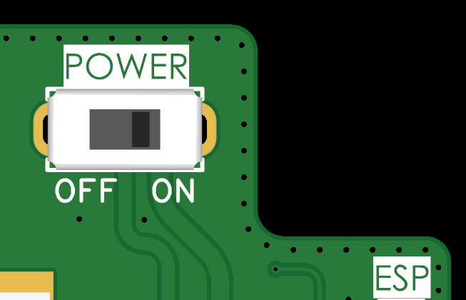
The ON/OFF switch.
Step 3: Power On
Move the switch from the initial OFF position (left) to the ON position (right).
Step 4: Initial Activation Confirmation
A few seconds after activation, the device's STATUS LED will begin to flash, indicating that the startup sequence has begun. Refer to 5. Datalogger Operation for interpreting the LED patterns.