2. Power Supply Methods
The ISURLOG features different power supply options to adapt to the greatest number of possible situations.
2.1. Power Supply Options
The ISURLOG features an integrated battery charger and power management circuitry, supporting three modes of operation.
Installation Note
For the step-by-step procedure on how to install and remove the batteries, please refer to the 4. Installation and Commissioning section.
2.1.1. Internal Batteries Only
The device has five battery holders on its upper part to accommodate a maximum of five INR18650 batteries, with a total capacity of 17000 mAh. It is not necessary to use all five batteries, and you may install one or all.
- Polarity Warning: The batteries must be placed respecting the polarities indicated on the PCB. Failure to respect the polarity could irreparably damage the PCB.
- Safety Requirement: It is important that all batteries connected to an ISURLOG have the same level of charge (same voltage).
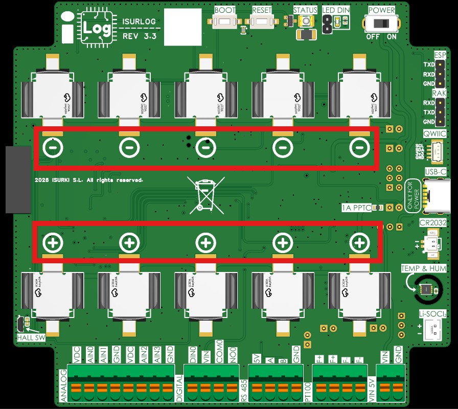
The five INR18650 battery holders — respect the polarity marked on the PCB.
2.1.2. External Power Only
The device can be powered externally without batteries. The power source must provide a voltage between 4V and 5V.
- Connection Points:
- USB-C Port: Located on the lower right side of the PCB. A conventional 5V mobile charger providing a minimum current of 1A can be used.
- Pressure Terminals (PIN 5V MAX): The last two pressure terminals on the lower right.
Caution
Do not use the USB-C port and the pressure terminals simultaneously as power sources.
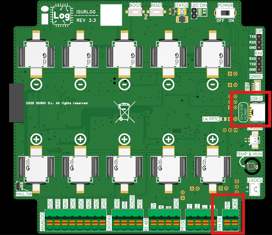
External power connections — USB-C port and PIN pressure terminals.
2.1.3. Batteries + External Power (Hybrid Mode)
The last option for powering the ISURLOG is to combine the batteries with external power. In this mode, the PCB uses external power while available, and switches to battery power when external power is interrupted. This mode is useful for running with batteries and a solar panel, or to continue functioning during external power outages. The batteries are kept charged by the integrated battery charger on the PCB. This charger charges the batteries at a maximum current of 400mA.
2.1.4. Non-Rechargeable Batteries (Li-SOCl2)
Hardware Note
This option is only available on ISURLOG v3.3 and later PCB revisions.
Starting with hardware revision v3.3, the ISURLOG adds a dedicated PH-2A connector, marked Li-SOCl2 on the PCB, to power the device from non-rechargeable lithium thionyl chloride (Li-SOCl2) batteries. This is a good fit for long-duration, low-maintenance deployments where periodic recharging isn't practical.
2.2. Jumper Configuration for Power Modes
Each of the power modes described in previous sections requires a specific jumper configuration on the ISURLOG PCB. It is completely necessary to configure these jumpers correctly to ensure a stable energy supply. The jumpers are located on the underside of the PCB.
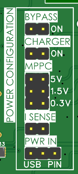
The power jumpers, underside of the PCB.
What I SENSE does
All battery current passes through the I SENSE jumper — as the name suggests, it's the point where current can be measured. In normal operation it must stay closed (ON position, shorted), as indicated below for every power mode. To measure the device's actual current draw, open the jumper and insert an ammeter in series across it — see Consumption Graphs for the full measurement procedure and real captures.
Batteries Only
For power only with batteries, the following configuration is needed:
- Charger: deactivated
- MPPC: The configuration of the MPPC jumpers is indifferent in this case, but the following configuration is recommended for the greatest energy efficiency:
- 5V deactivated
- 1.5V deactivated
- 0.3V deactivated
- I SENSE: ON Position
- PWR IN: Indifferent
External Power Only
For exclusively external power, the following configuration is needed:
- Charger: deactivated
- MPPC:
- 5V deactivated
- 1.5V deactivated
- 0.3V deactivated
- I SENSE: ON Position
- PWR IN:
- For power via the USB port, it is necessary to remove all jumpers from the PWR IN jumper.
- For power via the PIN port, it is necessary to connect pin 1 with pin 3 of the PWR IN jumper.
Batteries + External Power (Hybrid Mode)
For power with batteries + external power, the following configuration is needed:
- Charger: ON position
- MPPC: It is necessary to select only one of the three available input voltages.
- 5V: activated if the external power supply voltage is 5V, deactivated otherwise.
- 1.5V: activated if the external power supply voltage is 1.5V, deactivated otherwise.
- 0.3V: activated if the external power supply voltage is 0.3V, deactivated otherwise.
- I SENSE: ON Position
- PWR IN:
- For external power via the USB port, it is necessary to unite pin 1 and pin 2 of the jumper PWR IN, which is the USB position.
- For external power via the PIN port, it is necessary to unite pin 2 and pin 3 of the jumper PWR IN, which is the PIN position.
Non-Rechargeable Batteries (Li-SOCl2)
Hardware Note
The BYPASS jumper is only present on ISURLOG v3.3 and later PCB revisions.
For power exclusively from non-rechargeable Li-SOCl2 batteries via the PH-2A connector, the following configuration is needed:
- Charger: deactivated
- MPPC:
- 5V deactivated
- 1.5V deactivated
- 0.3V deactivated
- I SENSE: ON Position
- BYPASS: activated
Important
The Charger and all three MPPC inputs must remain deactivated whenever Li-SOCl2 batteries are used — these non-rechargeable cells must never be connected to the charging circuit.
Power Source Examples for MPPC Input
The MPPC (Maximum Power Point Control) input setting, used in Hybrid Mode, allows the ISURLOG to efficiently charge batteries from various low-voltage sources:
- 5V Input: This external power supply can be a 5V solar panel (equipped with a regulator, as many panels produce high voltage peaks even if the nominal voltage is 5V) or a standard 5V charger.
- 1.5V Input: This input voltage is typically compatible with a micro solar panel.
- 0.3V Input: This ultra-low voltage is often used with a TEG (Thermoelectric Generator), making the device suitable for energy harvesting applications.
2.3. RTC Backup Battery (CR2032)
The ISURLOG includes an ultra-low-power real-time clock (RTC) that keeps track of the current time. Under normal operation, this RTC is powered from the same 3V3 rail as the rest of the board — so when the datalogger loses power entirely, or is turned off with the POWER button, the RTC also loses power and the current time is lost.
This usually isn't a problem
The standard firmware includes automatic time-loss detection and resynchronization, on every connectivity variant (NB-IoT, LoRaWAN, or Wi-Fi): a lost RTC time is detected and corrected automatically the next time the device connects.
For installations where losing the time is critical, or for custom firmware builds that don't implement this resynchronization — or that operate purely as a local storage datalogger, without transmission — a CR2032 coin-cell battery can be connected to keep the RTC powered independently of the main supply.
- Connector: 2-pin, P=1.25mm pitch, labeled CR2032 on the PCB.
- Polarity: the positive pin is marked with an asterisk (*).
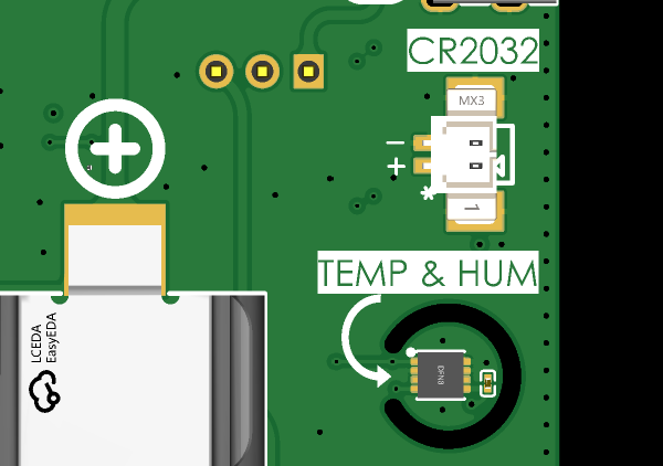
The CR2032 connector — the asterisk marks the positive pin.